
Double Overhead Cam (DOHC) timing explained
 Peter Larner putting together a rare DOHC Hart engine

|
|
|
Peter Larner putting together a rare DOHC Hart engine
|
From the archives: How to find the lobe centreline on double overhead cam engines
Double Overhead Cam Engines
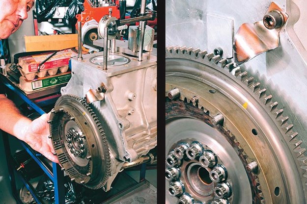
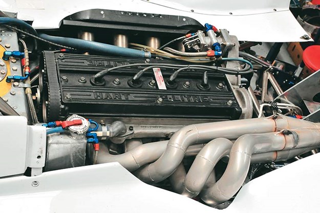
We’ve previously described how to fit and adjust various types of camshafts and associated valvetrain components, so this time we wanted to look at double-overhead camshafts (DOHC). We noticed this classic Hart engine being assembled in Peter Larner’s race engine workshop the other day and figured it was the engine on which to show the procedure. Many people won’t have heard of Hart engines but enthusiasts of classic racing will probably know the name. This is also an appropriate engine because of the method Peter uses to dial in cams.
From Unqiue Cars #318, Nov/Dec 2010
Though the Hart is extremely rare and unique, it has an exceptional pedigree. It’s named after its designer and builder, Brian Hart, who worked at the famous Cosworth company in the ’60s. He left Cosworth in 1969 to set up his own company and made engines for various racing classes including F2 and even supplied F1 engines for a number of teams into the ’90s.
In this engine the big-ends and mains are based on Ford sizes but the top end utilises a number of Cosworth components like the valve collets, retainers and valve springs, which brings us to the subject of getting the valvetrain set up correctly.
| Read next: How manifolds work
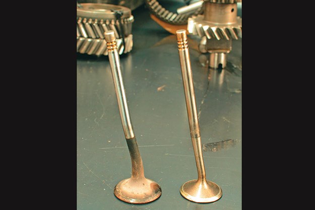 1. Bad things can happen inside your engine when your valve timing isn’t right! This bent valve would have dented the budget.
There’s more than one way
There are a couple of fundamental ways to match the position of the camshaft to the position of the engine internals during the building of a DOHC engine. The first, and simplest, is to determine lift at top dead centre (TDC).
Camshaft grinders often specify how much lift there should be when the engine is at TDC and using this method is simply a matter of setting the number one cylinder to TDC and ensuring that the cam is positioned so that it’s providing the specified lift or valve opening.
It’s a popular method because it’s so simple, but Peter suggests that it’s not the most accurate way. He prefers to use the lobe centreline method. With the lift at TDC method, the lift figure is specified, not crankshaft degrees (apart from setting the engine to TDC). The lobe centreline method can be considered to be an opposite approach because the position of the crankshaft is specified when the camshaft is at maximum lift and the valve is fully open. But with any method, the first thing that has to be determined is TDC.
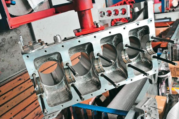 2. Although basic in construction by modern standards, this Hart racing engine is extemely sturdy.
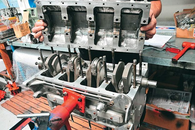
In an engine being built on a stand, it can be convenient to make a TDC mark on the flywheel/ring gear. To find and check TDC, set your dial indicator on the piston. Here, number four cylinder is being used because it’s next to the flywheel and on a four-cylinder engine it’s at TDC at the same time as number one, albeit on a different stroke. The head and cams aren’t on, so that doesn’t matter at this stage.
Turn the engine until you get the highest reading you can on the dial indicator. Then, to ensure complete accuracy, turn the engine forward three teeth, check the dial and note the how far the reading has dropped. Next, turn the crank backwards perhaps half-a-dozen teeth and then forward so that the marked tooth is three teeth before the pointer (turning it back more than three teeth and then forward will set the internal engine clearances to the correct positions).
Check the reading. It should be the same as the previous reading. If not, move the pointer a little toward the side where the reading dropped the most and repeat the procedure. Keep doing this until the dial indicator drops by the same amount when the flywheel is moved by three teeth either side. When it does, you’ve found TDC, exactly.
| Read next: Choosing the right gearbox
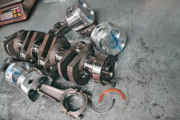 3. Quality components allow the Hart to spin to 10,000rpm.
Clearance to proceed
Before the cam can be dialled in, clearances between the base circles on the cams and the cam followers have to be set. Many ingenious systems have been invented over the years to adjust these clearances.
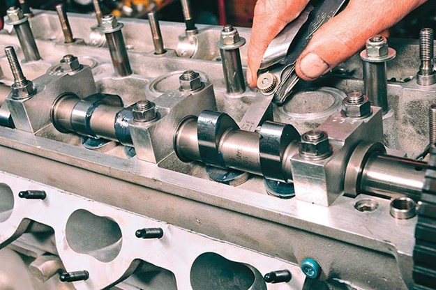
In this engine they are adjusted by fitting different thickness shims – or as the Americans say, lash caps – to the tops of the valve stems and then fitting inverted bucket type followers on top of them.
Different thickness shims are available to adjust clearances and the method is to measure the thickness of the shims with a micrometer before they’re fitted. Then the cams are fitted and torqued down and various thickness feeler gauges inserted to determine clearances.
There will be clearance specifications available for your engine. However, Peter says he never had the clearances for this Hart so he uses Cosworth settings, which are between 0.006" and 0.008" for the inlet valves and around 0.012" for the exhausts. Obviously, clearances on the exhausts are larger because they get hotter and expand more.
Getting clearances right on some engines can be extremely time consuming. Peter pointed to a Cosworth BDA he was working on and said it took him about sixteen hours to get it right because of the radically re-ground cams fitted to it.
 4. The main bearing caps are set into the dry sump in the Hart engine, which creates a strong bottom end.
In the end, he had to pull the head off and grind the valves shorter to make it all work properly. And, of course, that brings us to dialling in camshafts.
The lobe centreline method of setting up cams is as follows: After the engine is together and the cams in place and torqued down with the correct clearances, set the engine to TDC as discussed.
Mount a dial indicator on the number one inlet bucket follower with the base circle of the lobe on the bucket. The inlet valves will be closed. Zero the dial indicator.
Turn the cams until the marks on the drive sprockets (commonly referred to as gears) line up and then fit the timing belt. Timing belts are often directional and will usually be marked as such. The exact configuration of timing marks depends on your engine.
The variety of systems devised over the years is vast. One service manual I have lists nearly a thousand different marking schemes, and that’s just for relatively recent engines. The Hart uses the system shown.
When the cams are turned to line up the timing marks, note the reading on the dial indicator. It should match the figure for lift at TDC, as specified on the cam sheet. As mentioned, if the figures match some people leave it at that.
| Read next: How to upgrade classic brakes
 5. Peter Larner sets up top dead centre off the number four cylinder. This is the initial position.
A matter of degree
Mount a degree wheel to the nose of the crankshaft along with a pointer aligned with the TDC mark on the degree wheel as shown. Then, turn the engine until the dial indicator stops rising. At this point you’ll have reached maximum valve lift or valve opening.
Continue turning the engine until the dial indicator drops 0.020" lower than the maximum reading and note the figure on the degree wheel. In this case it’s 43 degrees.
Continue turning the engine until the valve closes completely and then keep turning until it starts to open again. Stop turning when the dial indicator reaches 0.020" before the figure for maximum lift. Take note of the reading on the degree wheel and add this reading to the first and divide the total by two.
The resultant figure, or quotient, will be the position in crankshaft degrees of the centreline of the lobe at maximum lift. If, in this case it were 161 degrees, the centreline would be at 102 degrees, which is about right for this engine.
However, the lobe centreline in the Hart is set at about 105.5 degrees because it develops more pulling power down low at that setting.
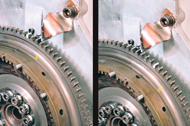 6. Three teeth past TDC (left); three teeth before TDC (right).
If the lobe isn’t where it’s supposed to be, the drive sprocket will have to be removed and an offset dowel fitted to alter the lobe position. Then, the test will have to be repeated until the figure matches that specified for the lobe centreline on the cam specification sheet.
The same procedure has to be carried out on the exhaust cam. Again, this can take quite a bit of time. It didn’t for this engine because all the figures were known, but for a new build with a re-ground cam and shaved head it could require a lot of adjustment.
It can get complicated so if you’d like it done properly, call Peter Larner Engines on (03) 9439 8986 or go to www.larnerengines.com.au.
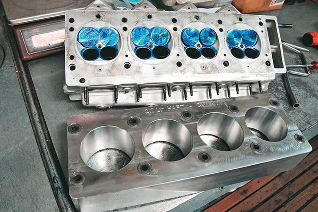 7. For best results, blocks should always be honed with a torque plate like the one pictured.
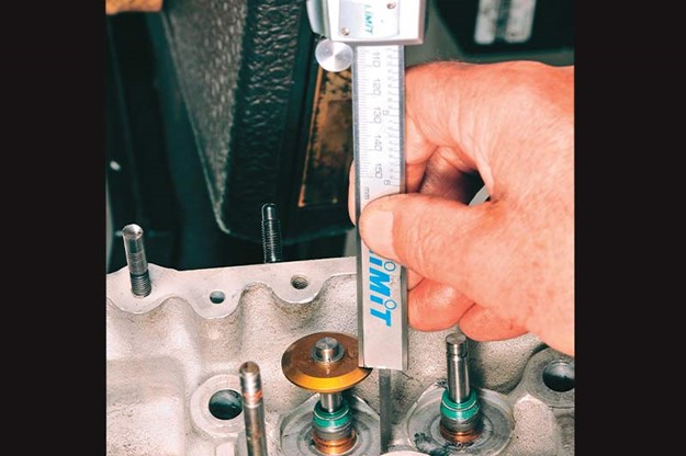 8. During assembly, valves are seated firmly and the installed height of the springs is measured (minus the retainer thickness).
 9. Springs are compressed to the installed height and spring pressure noted. It should match the spring’s specifications.
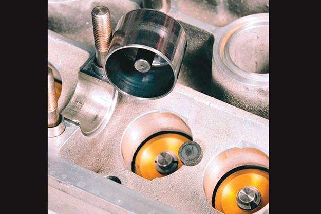 10. An inverted bucket follower and shim or lash cap.
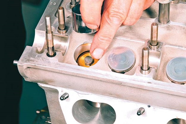 11. A lash cap is placed on the tip of the valve stem...
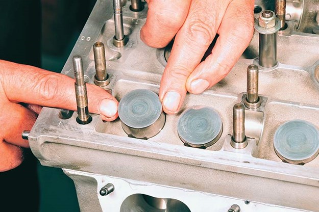 12...and the bucket follower is set in place.
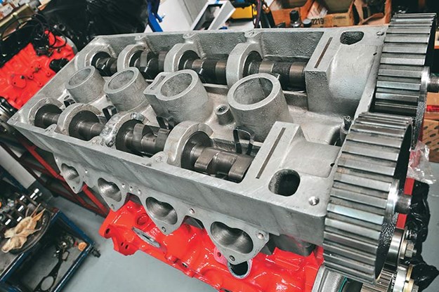
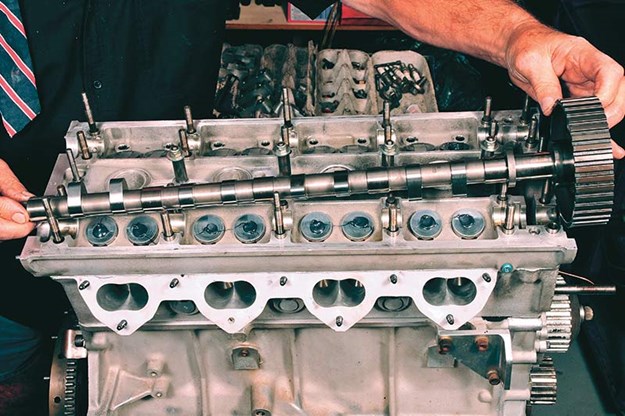 13. The camshafts are set in place.
 14. Measuring base circle to follower clearances.
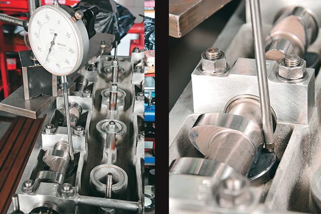 15. Set the dial indicator on one of the number one inlet followers at zero lift.
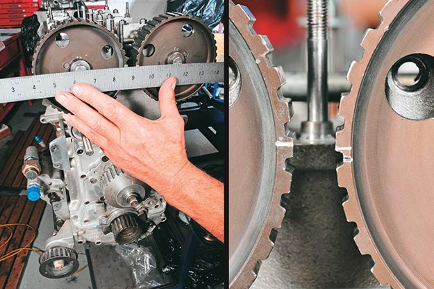 16. Lining up the marks on the cam drive sprockets.
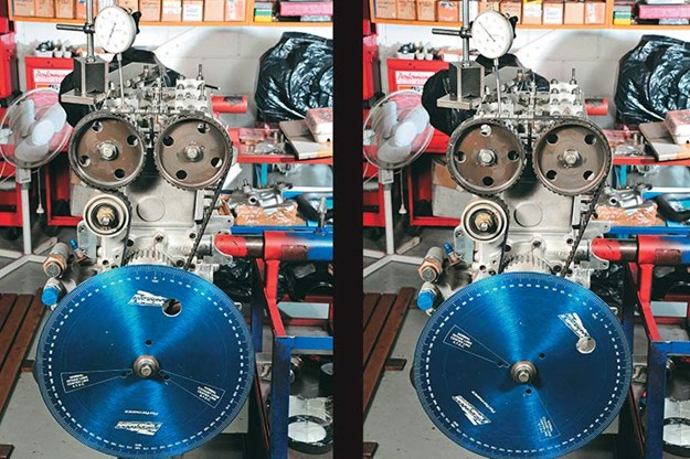 17. The setup for finding the lobe centreline. Taking readings from the degree wheel allows you to calculate the lobe centreline.
 18. The reassembled engine back in the car and ready to race.
 19. Basic methods work for any engine. On this Cosworth BDA, cams are slipped in from the front. The Hart’s drop into place more easily but the BDA doesn’t have caps/bridges that need to be torqued each time the cams are removed for adjustment.
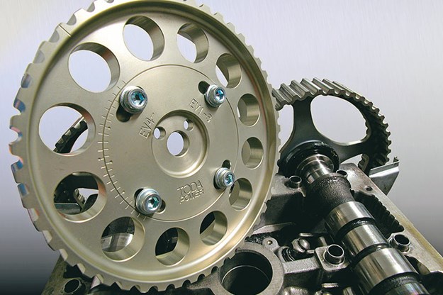 20. Adjustable drives are available for many engines.
Unique Cars magazine Value Guides
Sell your car for free right here
.jpg)
Get your monthly fix of news, reviews and stories on the greatest cars and minds in the automotive world.
Subscribe


.jpg)