Diff Spool - How to Toughen Up the Rear End of Your Car


|
|
Let's toughen up the rear end...
From Unique Cars #302
Although the differential is often at the rear of the car, it’s in the front line as far as performance is concerned. As engine performance is increased and stronger driveline components are needed to avoid breakage, the venerable Ford nine-inch differential, or an aftermarket derivative of it, is the standard choice for toughening up the rear end.
While original equipment nine-inch components are tougher than those in most other factory differentials (made for cars) they can still be broken quite easily in a powerful car.
Fortunately there’s a huge range of aftermarket performance parts that can be fitted into the basic Ford diff carrier. Here, well known race car builder John Taverna Jr. shows us how to replace the factory open differential case (non LSD) in this Ford nine-inch diff with the extremely strong full spool shown.
A full spool replaces the entire factory differential case with a solid unit and locks both axles together. This is most usually done in fairly powerful drag cars because they only have to travel in straight lines. However, it’s a relatively easy modification and showing how to fit it also covers a lot of what’s involved in fitting a rebuilt LSD, which is a separate subject we’ll cover in another article soon.
There’s no doubt that working on a diff can be a bit tricky and an expert will do it in far less time than you ever will. When you consider the costs and time involved in doing it yourself you’ll almost certainly be better off giving the work to someone with experience. But then, you won’t have done it yourself, will you? As always, torque specifications will be in your manual.
Don’t do any work on your car before obtaining a manual and reading through the relevant section. The parts needed are available from some parts suppliers individually or in kits, which are considerably cheaper. You may have to shop around to find them.
EFFECTS OF MOVING THE SPOOL AND PINION IN RELATION TO EACH OTHER...
• Moving the ring gear sideways away from the pinion increases backlash and moves the pattern closer to the upper edge of the teeth on the ring gear.
• Moving the ring gear sideways closer to the pinion decreases backlash and moves the pattern lower towards the base of the teeth on the ring gear.
• Inserting a thicker shim between the pinion retainer and the carrier moves the pinion forward and away from the ring gear. This increases backlash and moves the pattern further toward the outside end of the teeth on the ring gear.
• A thinner shim between the pinion retainer and the carrier moves the pinion closer to the ring gear. This decreases backlash and moves the pattern closer to the inside end of the teeth on the ring gear.
STEP-BY-STEP:
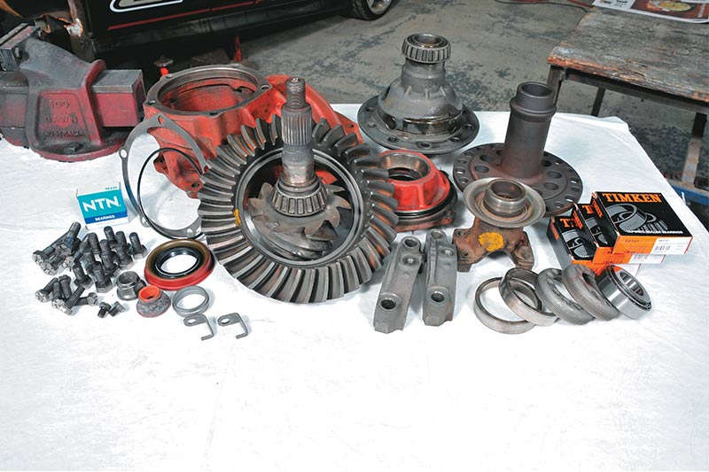
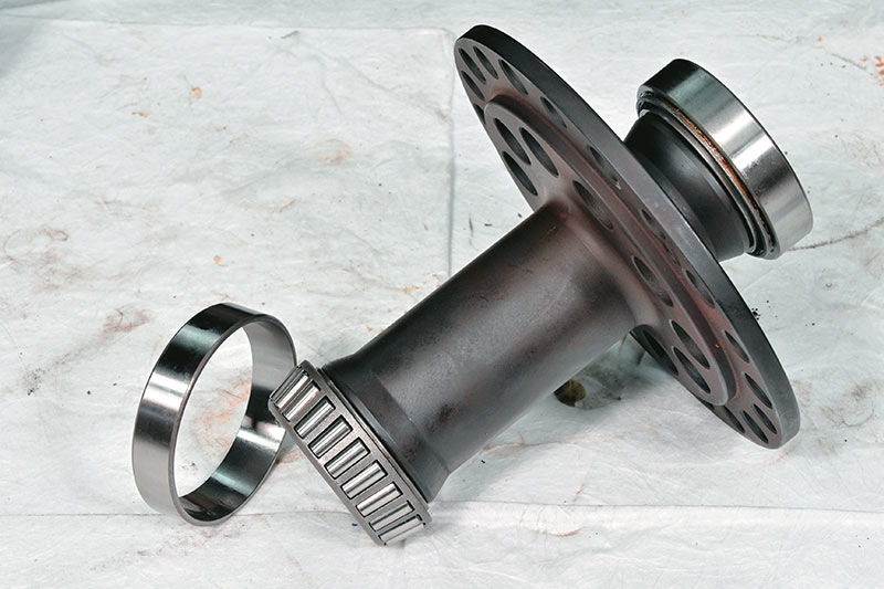
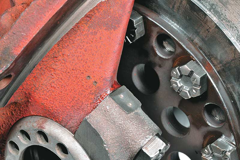
1. Once the differential carrier has been removed and dismantled you’ll have an assembly of parts that looks something like this. We’ve used the same names for parts that you’ll find in a Ford factory manual.
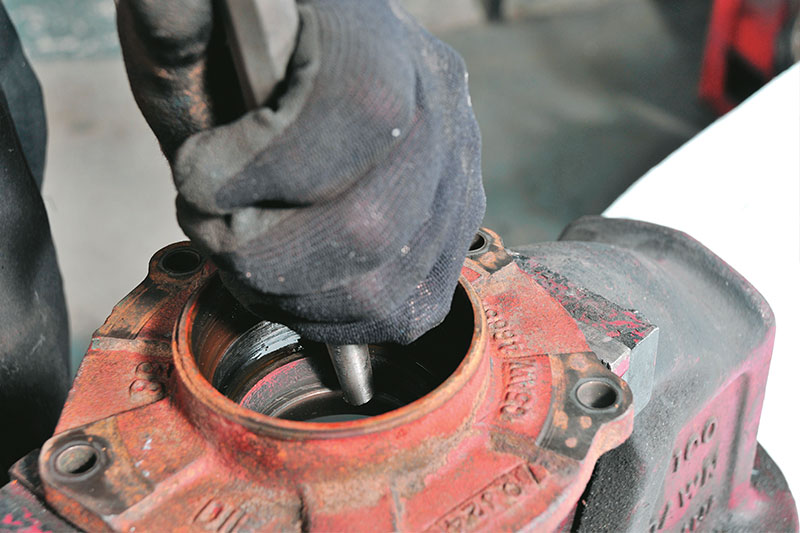
2. The bearing cups for the drive pinion can be tapped out using a pin punch set against the edge of each bearing cup. Tap firmly and work around the circumference of each cup evenly.
3. Tap each new bearing cup into place using the old bearing cup as a drift, as shown. As during removal, tap gradually and evenly around the circumference of each cup so that it goes in without misalignment in the bore.
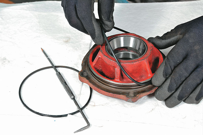
4. Remove the old O-ring and replace it with a new one. You can also see in this shot that the bearing cups are firmly seated in the bores of the pinion retainer.
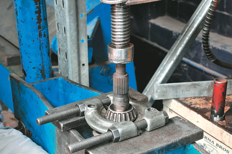
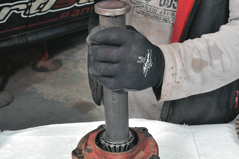
5. The old rear bearing has to be pressed off the drive pinion shaft. If you don’t have a press you’ll have to find a workshop to do this for you, although small presses capable of this job are actually available for reasonable prices these days. Note, too, that the drive pinion has to be pressed out of the retainer in this direction during disassembly.
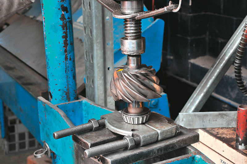
6. The new rear bearing has to be pressed onto the pinion shaft as shown. Alternatively, this bearing can be tapped into place using a tube of the appropriate diameter as a drift. However, the tube must make contact only with the inner race of the bearing.
7. Slip a new crush spacer onto the drive pinion shaft. This compresses as the flange retaining nut is tightened and governs pre-load in the front and rear pinion bearings.
8. Slip the pinion retainer onto the pinion then place the new front bearing on the shaft. This can be pressed or tapped into place using a tubular drift as shown. Again, make sure the tube makes contact with only the inner race of the bearing.
9a. Set the flange in place and fit a new lock nut. Set the flange firmly in a vice, as shown, and begin tightening the retaining nut with a socket. First, it has to be tightened gradually until all longitudinal play (movement of the retainer in alignment with the axis of the pinion shaft) disappears. Then, the nut is gradually tightened further until rotational movement of the retainer becomes firm.
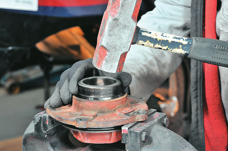
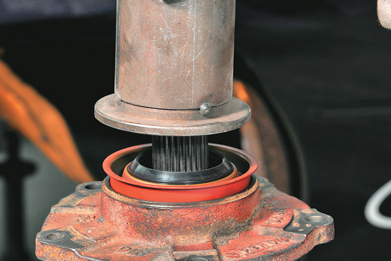
9b. The new seal should be tapped into place using a tubular drift as shown. Note that the rubber section of the seal sits proud of the metal section. Make sure any tooling used doesn’t make contact with the rubber or it will be damaged. These seals can also be set in place by gently tapping around the circumference evenly, however great care is required if doing so because if the metal is damaged or deformed, even slightly, the seal won’t work properly.
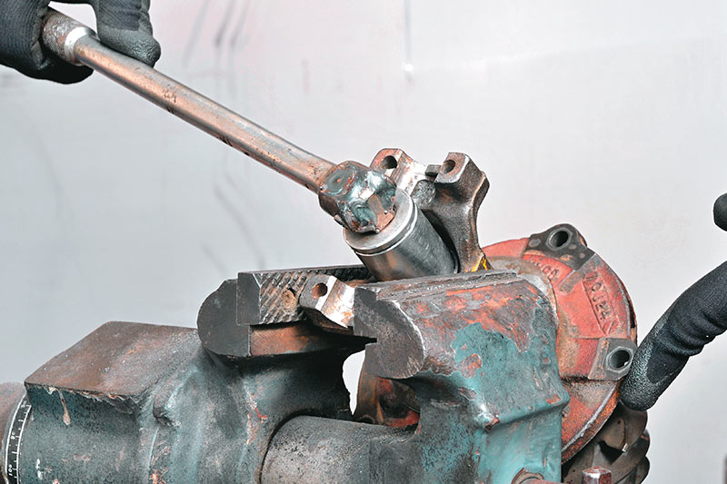
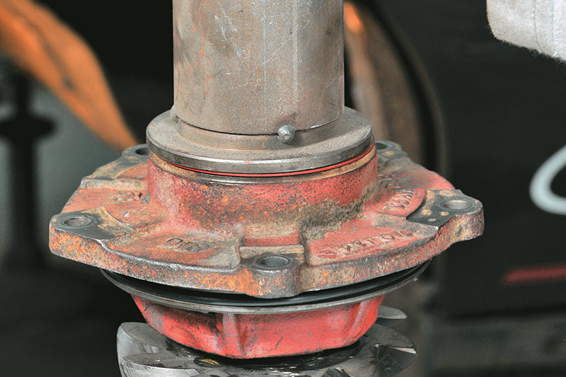
10a. You should be able to rotate the retainer smoothly with firm effort from just one finger. It shouldn’t stick and then start moving suddenly. Ideal tension occurs just before that stage. It should move immediately, as soon as firm finger pressure is applied. It takes quite a bit of effort to tighten the nut to this stage and an extension bar will be needed.
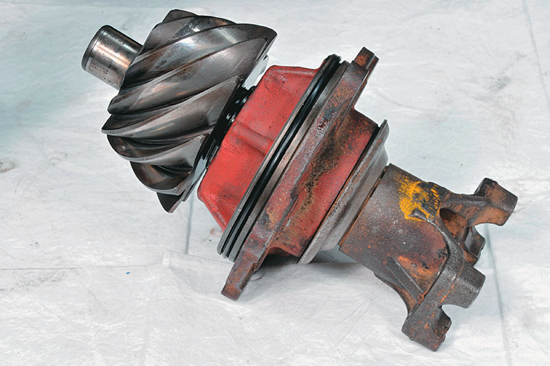
10b. This shows the fully assembled drive pinion, retainer and flange (yoke).
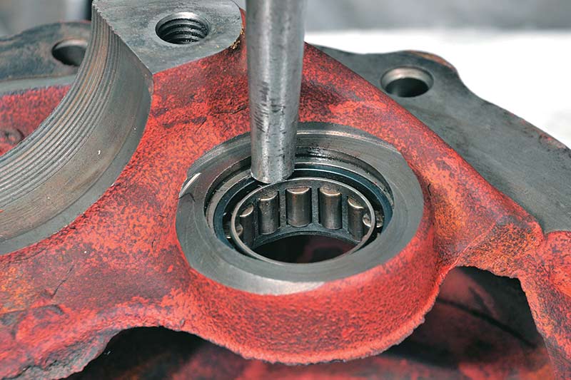
11a. The old pinion support bearing must be tapped out of the carrier and a new one pressed or tapped into place. Pressure should only be applied to the outer race in this case.
11b. When it’s firmly seated the pilot bearing retainer should be tapped into place. The angled tangs point away from from the bearing.

12. The drive pinion assembly can now be set in the carrier. Note the shim between the pinion retainer and the carrier. These come in different thicknesses and influence the mesh between the pinion and ring gear. If you’re using your original gears, you might be able to use the same shim. If you’re fitting new gears you’ll probably need to fit a different shim. More about that shortly.
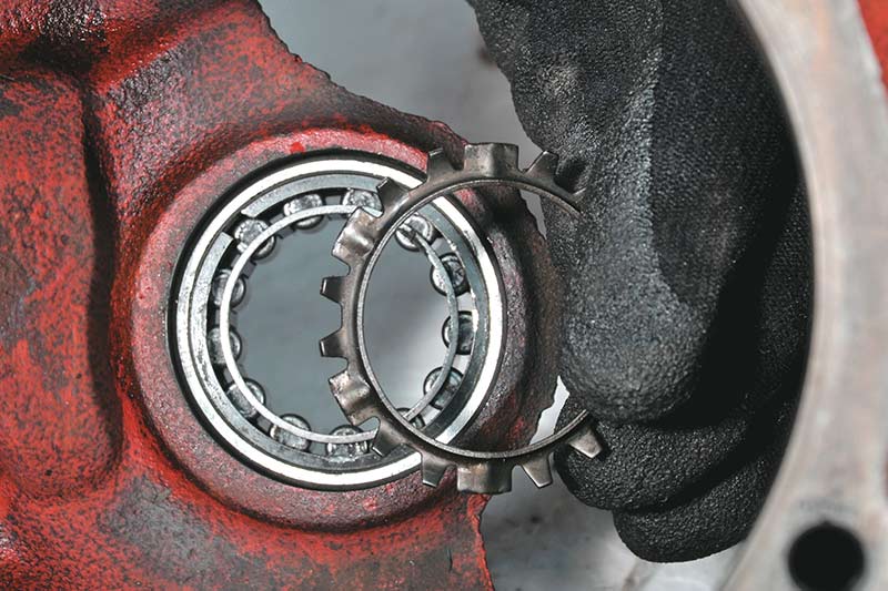
13. A new bearing is pressed, or perhaps tapped, onto each end of the full spool. Again, be sure to avoid applying any pressure to the cage. If you do, you’ll spread it and the rollers will fall out.
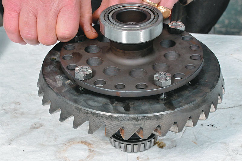
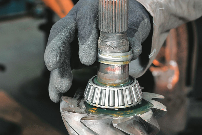
14. The ring gear is bolted on to the spool. The bolts are tightened evenly around the gear until it's firmly in place against the mounting flange. The bolts are tightened to specification in two stages.
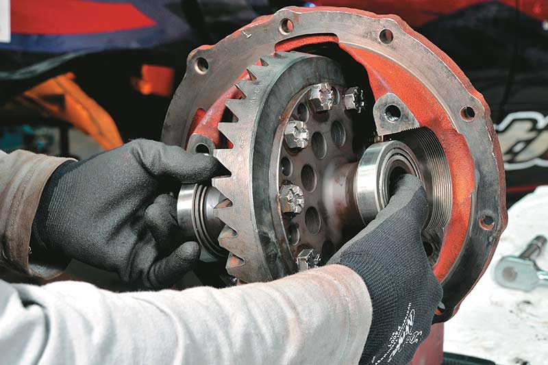
15. When fitting components it’s easiest to fix the carrier in a vice as shown. The spool is set in place with the bearing cones held on the bearings. All bearings should be oiled as they’re assembled.
16a. Bearing caps are not interchangeable. They must be put back on the side from which they were removed. To avoid mixing them up John puts two punch marks on the side of one cap and another couple on the side of the carrier to which it was fitted. Why two marks? John says he got caught once disassembling a used carrier. He put just one punch mark and then when it was pulled apart and cleaned he discovered that someone else had also marked it with a punch – on the other side!
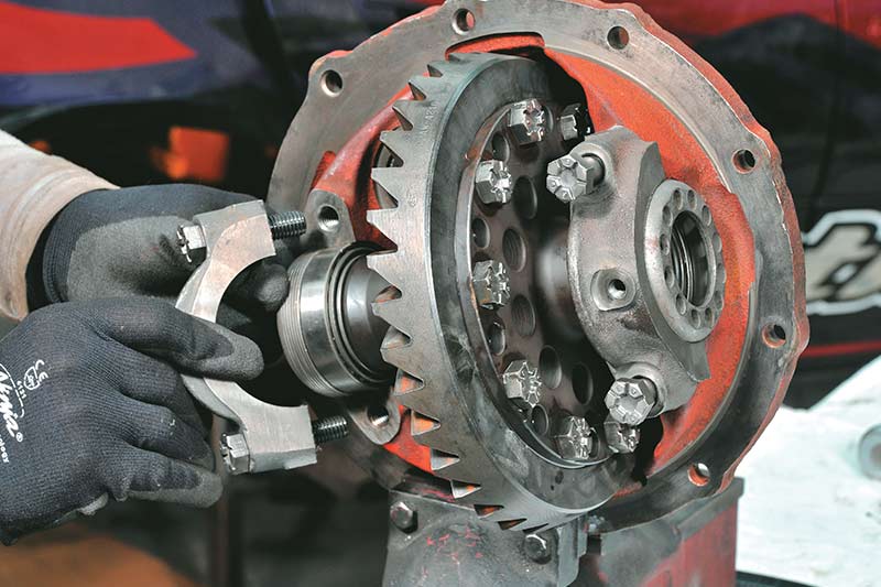
16b. The threaded side adjuster cups are set against the bearing cones in the threads in the caps and carrier.
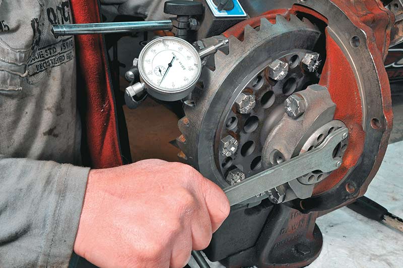
17. Backlash between the pinion and ring gear must be checked. Set a dial indicator as shown. Without moving the pinion, rock the gear backward and forward. Total movement should be between 0.008 and 0.012 inches. If it’s less than these figures (too tight) you must turn the side adjuster cups to make the ring gear move sideways away from the pinion gear. If backlash is greater than 0.012 (too loose) you must move the ring gear closer to the pinion gear. Make these adjustments until the back-lash is correct. You can use a grinder spanner to engage the holes in the adjuster cups.
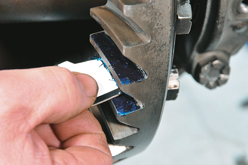
18a. In addition to total backlash you must also check the engagement pattern between the teeth because this will eventually become the wear pattern.
18b. Paste some gears with bearing blue with a drop of oil mixed in and turn the pinion until the pasted teeth mesh with the pinion teeth. Then, while simultaneously trying to prevent the ring gear from moving with one hand, turn the flange and pinion with the other hand. Applying resistance to the ring gear helps get a more accurate engagement pattern. Turn the pinion back and forth so that the relevant teeth mesh a few times. This will show you what the wear pattern will be in service.
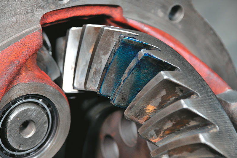
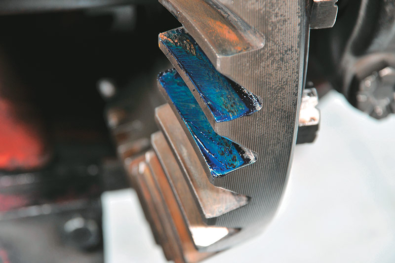
18c. It’s difficult to show with a photograph but the wear pattern should be placed fairly centrally on the teeth and it shouldn’t show any sharp edges. To make things even more difficult, you have to achieve this type of pattern on both sides of the teeth. That’s to say, on the drive and coasting sides. The fact is, that if it’s perfect on, say, the drive side and not so good on the coast side, the only way you can improve it on coast, or overrun, is to make it a bit worse on the drive side. It’s a balancing act.
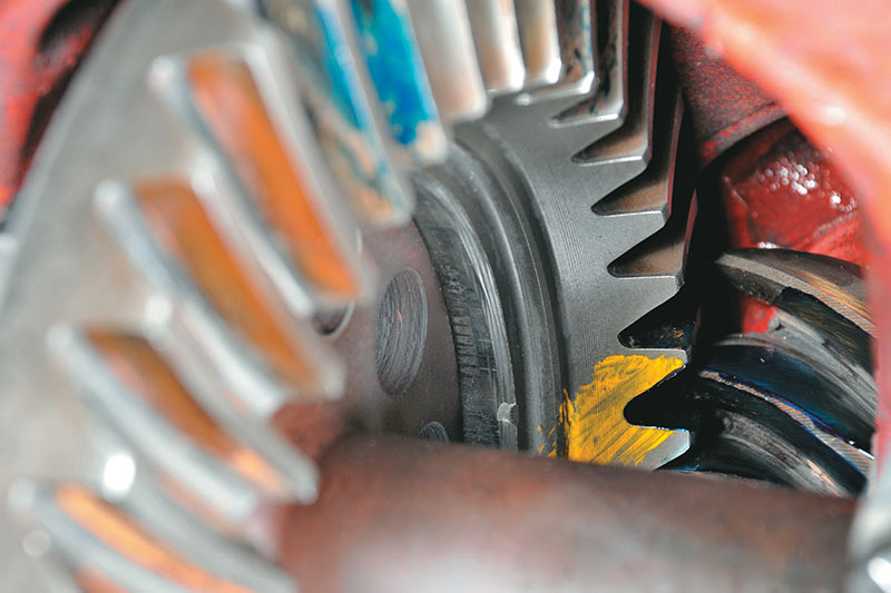
19. Note that gears are matched sets. Factory ring gears and pinions like these will have matching serial numbers marked on them. Also, gear teeth have to be meshed together in a particular way. Two teeth on a factory ring gear will have a notch between them at the inner end. Find it and mark the ends of the teeth on either side of it clearly. Yellow paint has been used here. One of the teeth on the pinion will also be marked with a line. The marked pinion tooth must be fitted between the marked teeth on the ring gear.
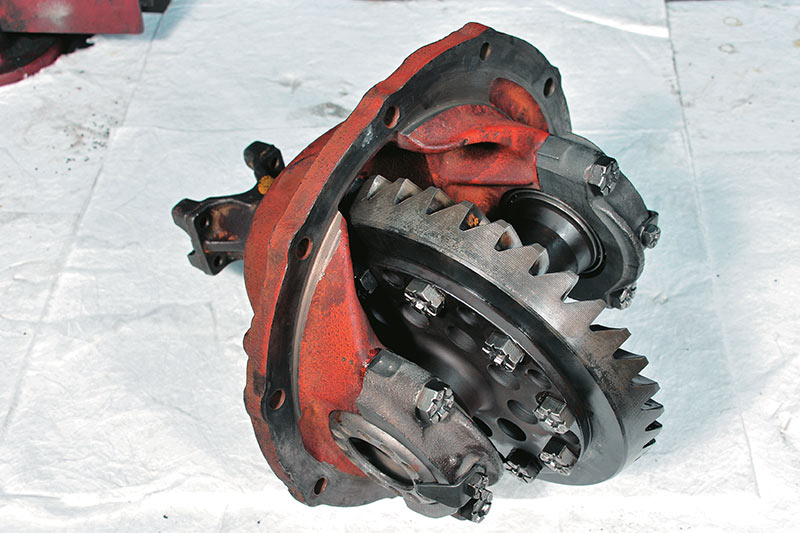
20a. The finished carrier with full spool fitted and ready for the strip. If you’re changing bearings alone you may not have too much trouble getting your adjustments correct. If, however, you change ratios you probably will have to spend quite a bit of time checking and adjusting.
20b. Once you do get it right a locking tab is bolted to each cap and the pointed section of each is tapped into one of the holes in the threaded adjusting cups to make sure it can’t move in service.
Unique Cars magazine Value Guides
Sell your car for free right here
.jpg)
Get your monthly fix of news, reviews and stories on the greatest cars and minds in the automotive world.
Subscribe